Goals
I wanted to build a “full” factory system on one piece of 500x500mm plywood. Of course, I can’t fit an entire factory onto a plank of wood, but a PSU, PLC, Switch, some I/O, some terminals, and a few cable runs would be enough to get me most of the way there. If you want the more detailed breakdown of all the parts, check out the build design article.
- Test our hardware
- Mount it to the board
- Enable the services we want on the PLC
- Program our PLC
The Rig
First Boot
Before drilling anything down, I wanted to boot the PLC up and have an initial play around. I wired up the PSU, PLC, and Switch on my desk, and made sure everything booted and worked as expected.
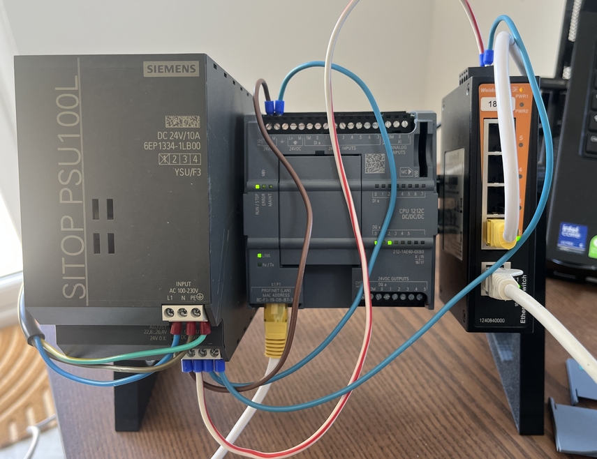
I’d recommend doing this first to make sure everything is working, especially if you bought second hand like me.
I also did a second test with all the I/O, terminals, and MCB - again, to make sure everything was functioning the way I expected it to.
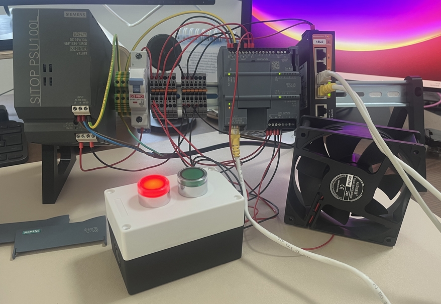
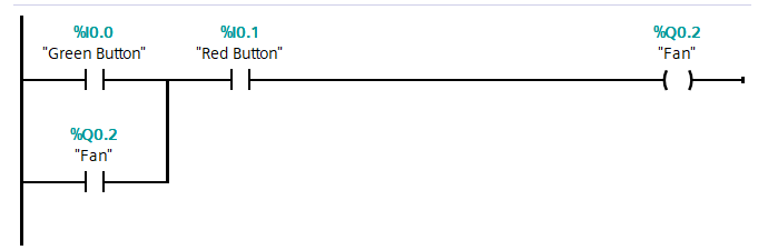
This also gave me a chance to start learning TIA Portal - the software used to program Siemens PLCs. I wrote some simple ladder logic to make the green button turn on the fan, and light the green LED, and the red button turn off the fan, and light the red LED.
Mounting the Hardware
Once I was happy everything worked well, it was time to start deciding how to lay it all out.
I’d already created a wiring diagram using the dimensions of all the devices to determine the size of the board I would need, so it was just a case of making sure I’d done my maths correctly.
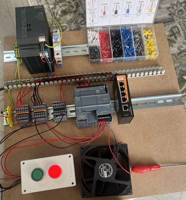
I started by laying the core components out on the board, mounted to their DIN rails.
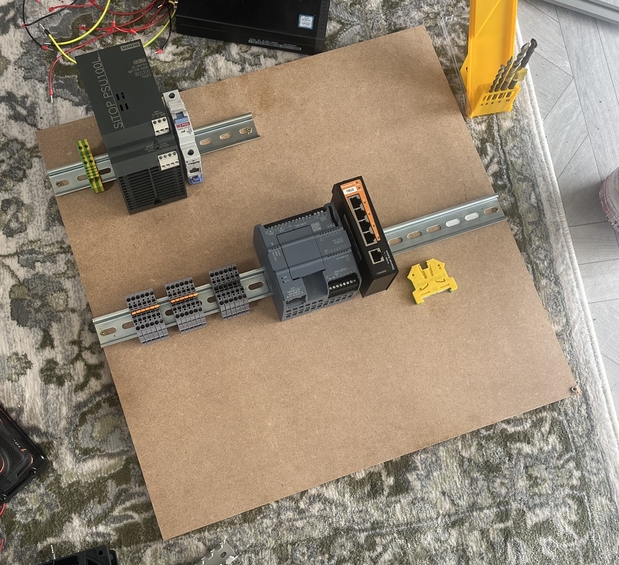
Then it was a case of mounting things down. I used 10mm long screws so as not to break through the 12mm thick board. One mistake I made was not using washers the first time, making the mounts pretty frail. I picked up some washers and it made a world of difference to the security of the mounts.
Making it Pretty
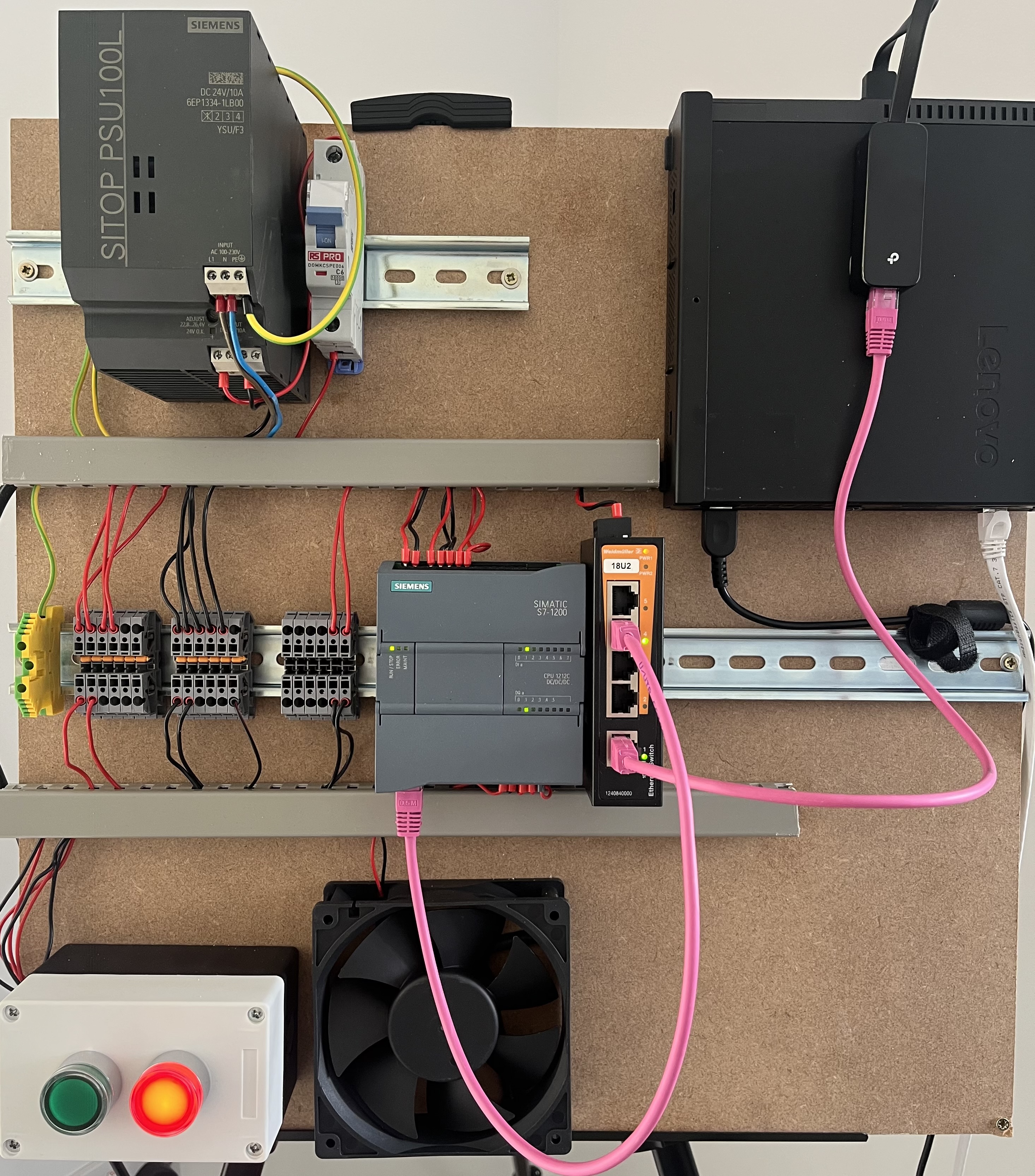
And finally, some cable management. I didn’t buy any cable trunking until I saw how much of a mess I had made. I had looked online for some previously, but struggled to find what I was looking for, until I came across the right terminology of “open slotted trunking”. I picked up 2 metres (the smallest I could find) of 25mm trunking and cut it down to the sizes I needed.
I got the PC mounted using a generic bracket I picked up on eBay, and a USB-Ethernet interface to add the extra port I needed for the firewall.
I picked up an easel to display the board on. I did consider mounting it to my wall, or putting up a new shelf for it, but I’m just not ready for that level of commitment. The easel does everything I want, and it’ll make it easy to move around if I need to.
PLC Configuration
I won’t go in depth about exactly how I configured my PLC (lest I embarrass myself terribly) but I’ll give you the highlights and the resources I found helpful. I do share these diagrams hesitantly, as I have 0 formal training with PLCs.
Modbus
One of the first things I did was set up the Modbus server on my PLC. If you’ve never worked with PLCs or ladder logic before, this will seem a strange way to enable a network service (at least, I thought so!) but it’s all part of the learning experience.
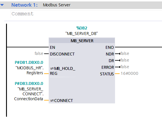
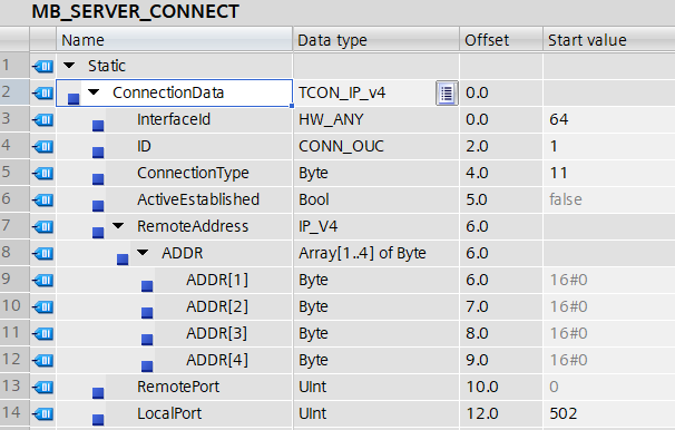
This is a great tutorial for getting your PLC up and running in TIA Portal, as well as setting up the Modbus server. The main thing I did differently was making it less secure by leaving ‘Remote Address’ in the MB_SERVER_CONNECT block as 0.0.0.0. We’ll discuss this more in the attack and defend sections of the series.
OPC-UA
I’ve mentioned OPC-UA a few times now without diving into much detail, but rest assured, we’ll discuss it more in the next part of the series when we look at UNS.
Enabling OPC-UA is slightly more straightforward than Modbus, but there was one thing that caught me out a couple of times: The DBs must be specified in the OPC-UA server interface under PLC->OPC UA Communications. Otherwise, they won’t be accessible via OPC-UA.
This is another good tutorial on setting up OPC-UA. Worth noting, I made mine as insecure as possible.
PLC Tags
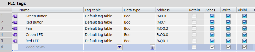
Tagging the different I/O addresses makes the ladder logic way easier to read and write. Here are my final tags, I’d suggest you do the same for your own sanity!
Monitoring DB
I made a second data block to store the status of the LEDs and fan. This would give me something to monitor later in the UNS and SCADA system and also allowed me to control these components remotely.

Final Ladder Logic
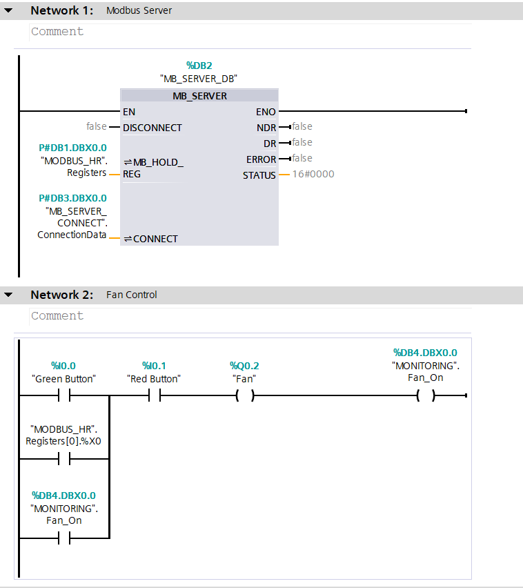
The final ladder logic is still very simple. The first block controls the Modbus server, as discussed above. TThe second network controls the fan. It switches on if any of three things are true: the green button is pressed, Modbus register 0 is set to 1, or the MONITORING.Fan_On tag is true. Turning on the fan also sets MONITORING.Fan_On to true, so the rung latches - the fan keeps spinning after I let go of the button. Pressing the red button breaks the latch, switching the fan off and setting the tag back to false.
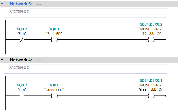
The third section controls the red LED. When the fan is off, the red LED is on, and the corresponding monitoring tag is set to true. The fourth section does the opposite. When the fan is on, the green LED is on, and the corresponding monitoring tag is set to true.
Lessons Learned
- Use washers! - This is just showing my inexperience with anything DIY. Using the washers made mounting the DIN rails, button box, cable trunking, and server mount far more secure. No more worrying about things falling off.
- Get cable trunking - I thought I’d be fine without it, until I saw the mess of red and black. Just buy it and mount it from the start to make life easier.
- Label and tag - I didn’t do this at all, and I wish I had. Now, my wiring is a bit of a mystery and it makes troubleshooting or rebuilding much harder. Next time I do one of these builds, I will be getting some labels or tags and using them accordingly.
- Specify your DBs for OPC-UA - When I added the MONITORING DB, I did spend longer than I want to admit figuring out why I couldn’t access it via OPC-UA.
- Use PLC Tags - Makes life much easier when reading and writing the ladder logic.
Final Thoughts
If you’re more experienced than I am with PLCs, you might be tearing your hair out reading this article. If so, please feel free to contact me and tell me all the things I’ve done wrong so I can improve it. In the next article, we’ll build the UNS system!