Goals
In building my OT lab, I had a few goals in mind:
- Learn more about industrial equipment and wiring
- Create a playground for learning and testing
- Build a platform to demonstrate OT attacks and risks
The Hardware
PLC
I picked up a second hand S7-1200 DC/DC/DC CPU for my build. I wanted to go with real industrial gear, rather than something like a ClickPLC, to make the build more realistic. It also gave me an opportunity to get hands on with one of the most popular PLCs on the market.
Of course, the S7-1200 isn’t cheap if you’re buying brand new, but with a bit of patience, I ended up getting a pretty good deal on eBay, picking mine up in near mint condition. If you want to do the same, check out my buyers guide here.
PSU
The PSU was another second hand pick up. I found a SITOP PSU100L going cheap and snagged it at a good price. It is overkill for this build but a deal’s a deal, and it matches the PLC nicely.
All you really need is a way of supplying 24VDC - for most people, a couple amps should be fine.
Switch
The Weidmuller IE SW BL05 STX was another eBay find. Truthfully, I thought I was getting a managed switch (shame on me for not doing my research!) but I’m still glad I picked it up, as having a DIN rail mounted switch looks quite smart.
It provides a convenient way of connecting other computers and devices into my factory network.
Server
I used a Thinkcentre M710Q MiniPC I had lying around. It does the job of running a handful of VMs just fine, it’s quiet, and doesn’t draw too much power.
BOM
This table encompasses nearly all of the parts of my build. All the links are for UK sites.
| Item | Link | Notes |
|---|---|---|
| Siemens S7-1200 CPU | I got the DC/DC/DC variant with 4.x firmware - IMO the best option for hobbyists. The DC/DC/DC model runs entirely on 24VDC which keeps the wiring simpler and safer. | |
| 24VDC PSU | I picked up a Siemens SITOP PSU100L on eBay - massively overspecced for this project, but I got it cheap and it’s built like a tank. Any PSU that can supply 24VDC at a couple of amps will do the job. You’ll also need a way to power it from mains - I stripped a kettle lead and wired it straight in. | |
| DIN Rail | RS Components (500mm) | I used a 250mm rail on the top for power components and a 500mm rail on the bottom for everything else. |
| Piece of wood | A 12×500×500mm sheet of ply that I had cut at my local B&Q for a fiver. Does the job. | |
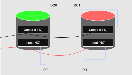
| Green LED Push Button | eBay | Works as both input and output - the LED is wired to a PLC output, the button to an input. I wired it as NO (normally open). |
| Red LED Push Button | eBay | Same as above. Wired as NC (normally closed). It’s wiried NC so that broken wire or loose ferrule opens the circuit and reads just like a press - a fault stops the fan spinning rather than just breaking the button. |
| 24VDC Fan | Amazon | Simple on/off fan as a physical output to demonstrate control. Could be swapped for a PWM fan if your PLC supports it (which mine does, I just couldn’t find a 24VDC PWM fan that was big enough). |
| Terminal Blocks | RS Components | Used for distributing power and routing signals around the panel. I bought 20 and used most of them. |
| Jumper Bars | RS Components | For bridging power across adjacent terminals. Cut them down to the length you need. |
| MCB | RS Components | Adds overcurrent protection and doubles as a clean on/off switch for the whole panel. |
| Earth Terminal Blocks | RS Components | For earthing the PLC, PSU, and DIN rails. Don’t skip this!! |
| Red Wire | Amazon | +24VDC. I bought 10m. |
| Black Wire | Amazon | 0VDC. I bought 10m. |
| Ground Wire | Amazon | Earth/ground connections. |
| Bootlace Ferrules | Highly recommended - they make a much cleaner and more reliable connection in spring terminals than bare wire ends. Get a crimper to go with them. | |
| Button Box | Amazon | Plastic enclosure for mounting the buttons neatly on the panel. |
| Wire Duct | CEF | Slotted trunking to keep wiring tidy and routed cleanly - makes the build a lot cleaner looking. |
| Mini PC / Server | For running the SCADA, gateway, MQTT broker, and firewall. I used a Proxmox server with VMs, but any Linux machine will do. | |
| Network Switch | To connect the PLC, server, and laptop on the factory network. I grabbed a Weidmuller IE SW BL05 STX unmanaged switch - it was a random eBay find. A managed switch would give you a lot more to play with from a security perspective, but costs accordingly. | |
| Stand | Amazon | An art easel for holding up the board. |
Diagram
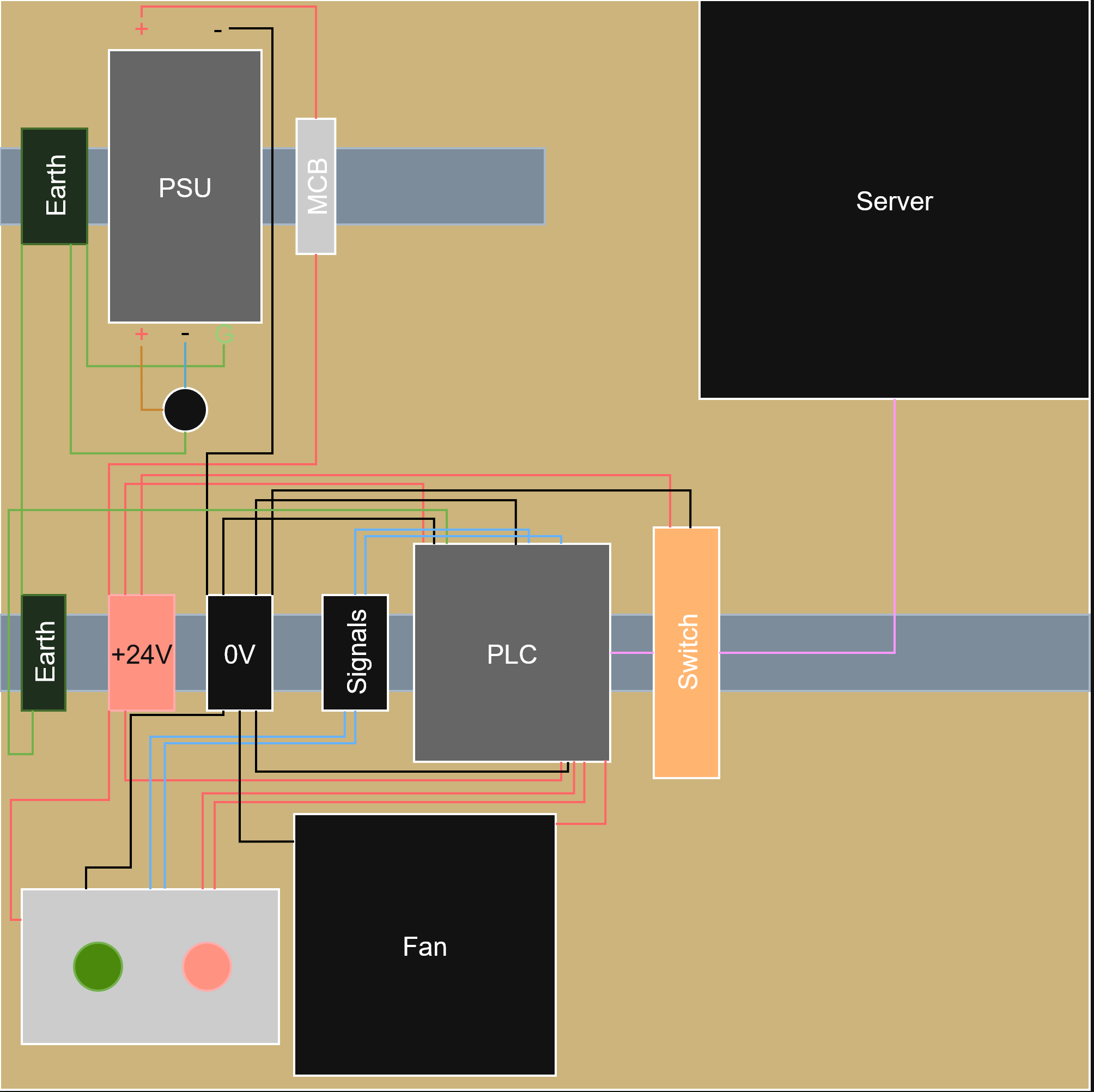
Below is a simple drawing of my hardware set up with wiring. It’s not the prettiest thing but it should give you a rough idea of how everything is wired up.
This diagram is just for the buttons, since it isn’t clear from the pictures or diagrams as to how they’re wired. It’s a very standard set up.
The Network
Segments
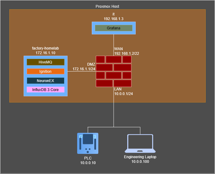
I split my network into three segments - Factory/OT, DMZ, and IT. The network is split using an OPNSense firewall running virtually on our server. I had to pick up a USB NIC to make this work - not a great solution for a real factory, but does the job well for our homelab.
- The Factory network is where the PLC and switch live.
- The DMZ network hosts the SCADA, Unified Namespace (UNS), and any other industrial systems.
- The IT network hosts read-only systems like dashboards.
This is to mirror what is commonly found in industrial networks, where the OT network is separated from the IT network via a DMZ, and any traffic wanting to travel from IT<->OT has to first go through the DMZ.
| Network | IP/Subnet | Purpose |
|---|---|---|
| OT/Factory | 10.0.0.0/24 | Host industrial devices |
| DMZ | 172.16.1.0/24 | Host systems that need to speak to IT and OT |
| IT | 192.168.0.0/22 | Host IT Systems |
Diagram
Why don’t you put the SCADA system in the OT network?
Good question, and you totally could. I might even do that in the future. In reality, it depends on your company, past network design decisions, and business requirements. There’s never a ‘one-size-fits-all’ for network design - it will always be at the behest of the business, even if it’s unwise.
The Systems
Factory/OT
There aren’t many systems to speak of in the factory portion of the network, but there are a few services worth mentioning.
The PLC exposes a few different services, including:
- OPC-UA Server - this can be used to read, write, and subscribe to tags on the PLC.
- Modbus Server - configured via a
MB_SERVERblock in the PLC code. Allows coils and registers to be read from and written to by a Modbus client - HTTP Server - exposes information about the PLC, and can also be used to administrate it
- S7comm - Siemens’ own, proprietary protocol
All these services can pose their own risks to the system (depending on how well configured/hardened they are) and will be explored further in the “Attack” portion of this series.
DMZ
The DMZ is where the data actually starts moving around. Everything here runs in Docker on a single Ubuntu Server VM (project name factory-homelab), which keeps it tidy and easy to tear down and rebuild when I inevitably break something.
- HiveMQ CE - the community edition of the HiveMQ broker.
- NeuronEX - a gateway that can read OPC-UA from the PLC and send it to HiveMQ as MQTT.
- Ignition - the SCADA system. I used the Maker Edition which is free!
- InfluxDB 3 Core - a very basic historian which will store our data for visualisation, fed by the UNS.
- Caddy - reverse proxy for serving applications over pretty subdomains, and providing HTTPS.
I wanted Ignition to be able to subscribe directly to the gateway via MQTT, but the plugin required to do that does not support maker edition. Therefore, I had to compromise and have the SCADA system connect directly to the PLC over OPC-UA, breaking the UNS best practice.
So how does a value actually get from a button on my panel up to a dashboard? Roughly like this:
A tag changes on the PLC (say the fan kicks on). NeuronEX is polling that tag over OPC-UA, sees the change, and publishes it to HiveMQ as an MQTT message. From there anything subscribed to the broker can pick it up (e.g. InfluxDB in the DMZ network, to then be displayed by Grafana)
IT
The IT network is all read, no write. They’re allowed to watch the plant, but they’ve no business touching it. That’s the entire reason this stack lives up in IT rather than down in the DMZ or OT: it only ever pulls data, never pushes it.
It’s another Ubuntu Server VM running two things in Docker:
- Grafana - draws the pretty pictures - fan state, the LEDs, operating mode, that sort of thing.
- Caddy - reverse proxy for serving applications over pretty subdomains, and providing HTTPS.
This part of the network is for the enterprise folk who need to see the data, but should never be able to write anything back down the network.
Final Thoughts
In this article we’ve laid out our plans for the lab - from hardware to networking to systems. The next several articles will cover the building process, starting with putting together the physical rig.